
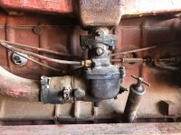
Hello guys. Trying to get this 2606 back together. I had always thought the engine was a C263. During the engine rebuild we figured out it was a C221 and due to a lack of pistons we ended up boring it out to a 301. At one point in this process a few years ago I ordered a rebuilt carb for a C263 I think from YT and sent mine back as a core. I can't find a picture of the old one installed but this new
![20240404_155712[1].jpg](https://forums.yesterdaystractors.com/attachments/20240404_155712-1-jpg.65819/ "20240404_155712[1].jpg") one interferes with the oil fill tube. I don't know if it is the carb or maybe the tube needs to be driven in further. I can always rig up some kind of cap for the tube if necessary. Pic is attached. Any ideas? Thanks.
one interferes with the oil fill tube. I don't know if it is the carb or maybe the tube needs to be driven in further. I can always rig up some kind of cap for the tube if necessary. Pic is attached. Any ideas? Thanks.
You are using an out of date browser. It may not display this or other websites correctly.
You should upgrade or use an alternative browser.
You should upgrade or use an alternative browser.
- Thread starter bc
- Start date
wore out
Well-known Member
I have a 544 hydro with a similar (but 4 cylinder) engine. When I got it there was a similar clearance issue, my engine has been swapped (yellow engine vs. red tractor).Hello guys. Trying to get this 2606 back together. I had always thought the engine was a C263. During the engine rebuild we figured out it was a C221 and due to a lack of pistons we ended up boring it out to a 301. At one point in this process a few years ago I ordered a rebuilt carb for a C263 I think from YT and sent mine back as a core. I can't find a picture of the old one installed but this new View attachment 65819one interferes with the oil fill tube. I don't know if it is the carb or maybe the tube needs to be driven in further. I can always rig up some kind of cap for the tube if necessary. Pic is attached. Any ideas? Thanks.
Turns out it had the wrong dipstick tube, was supposed to have a curved dipstick tube like the one pictured below. I found a N.O.S. tube on the 'net, and a used, correct dipstick. However, looking at the Parts Catalog, I don't see a curved tube listed for your tractor.

Another thing, is the direction of the carb air inlet correct, in other words does the air intake tube go forward?
Otherwise, it might be possible you have the wrong carb and need one with the throttle lever on the other side so the air inlet would face backwards, out of the way of the dipstick tube.
BarnyardEngineering
Well-known Member
- Location
- Rochester, NY
Carburetor is on backwards. The inlet should be facing to the rear of the tractor. You've got a carburetor for a 656 there. What you need is a carburetor for a 460 or 560 because I doubt you can buy one for a 606 specifically.

BarnyardEngineering
Well-known Member
- Location
- Rochester, NY
560 carburetor (what you need):

656 carburetor (what you have):

656 carburetor (what you have):
Well Crud. Thanks. Right now I just want to get this thing running. I didn't do anything to the gas inlet tube so the prior carb must have had a front facing gas inlet. Think I put about 2 kits in the old carb before giving up on it and always ordered kits for a C263. Always had issues with rust in the gas tank. It never had an air cleaner and I ended up running an L shaped piece of plastic pipe up into a modern style McDonald air filter. It had one of those electric gas shutoffs on the bowl which I think pointed to the rear but I took it off and put in a needle valve. However I didn't have any problems getting to the oil tube so who knows.
I'm thinking I could reverse the top butterfly and mount this carb the other way but I guess I better check to make sure the butterfly works like it is supposed to now since the pic of the 560 carb has the arm pointing down and the 656 one is pointing up like mine. I just know that the carb that was on there always had a 1 3/8" throat which matches the manifold and some of the others had a smaller inch and a quarter throat.
Somewhere on an old phone or computer I got pics from 17 years ago back when I bot it. I know I posted pics here at the same time on the old website system but I couldn't find them doing a search yesterday. Unless they are buried somewhere on this site.
I've hunted around and can't find any old pics but I'm fairly sure it had a front facing carb intake before. At some point it had an engine replacement which I believe was a C221 from a combine, possibly a 303. I can't just turn the butterfly around because the one side has a little stud for a screw stop on it. What I don't know is whether the butterfly will be open or closed when and if it starts. The difference between the two pics above by barnyard is that one lever is up and one is pointing down. After attaching the governor rod to the carb lever on mine that points up and then when the lever on the governor is in the forward position (towards the front of the tractor) the carb butterfly valve is closed. When the governor lever moves back then the carb butterfly opens up. If that is how it works then I am OK.
My goal is to get the engine running next week. I tried hammering the tube down further and it doesn't move. I will add the 9 quarts of oil and check the level afterwards as well as after it has run for a while. If I need to I'll shorten up the rod in the top of the stick and use pliers or else cut down the tube and stick and make new marks on the stick.
Since I had that C221 bored out to a 301 then I may be playing around with jets or whatever to get it to run right anyway. Thanks.
Janicholson
Well-known Member
To assure no runaway, with tractor not running, move the hand lever at the dash to full idle. The governor rod will now be trying to pull the throttle closed to its idle stop.I've hunted around and can't find any old pics but I'm fairly sure it had a front facing carb intake before. At some point it had an engine replacement which I believe was a C221 from a combine, possibly a 303. I can't just turn the butterfly around because the one side has a little stud for a screw stop on it. What I don't know is whether the butterfly will be open or closed when and if it starts. The difference between the two pics above by barnyard is that one lever is up and one is pointing down. After attaching the governor rod to the carb lever on mine that points up and then when the lever on the governor is in the forward position (towards the front of the tractor) the carb butterfly valve is closed. When the governor lever moves back then the carb butterfly opens up. If that is how it works then I am OK.
My goal is to get the engine running next week. I tried hammering the tube down further and it doesn't move. I will add the 9 quarts of oil and check the level afterwards as well as after it has run for a while. If I need to I'll shorten up the rod in the top of the stick and use pliers or else cut down the tube and stick and make new marks on the stick.
Since I had that C221 bored out to a 301 then I may be playing around with jets or whatever to get it to run right anyway. Thanks.
Then move the hand lever to full open. The rod to the carb will now be opening the carb all the way. if it is backwards it will not work and could overspeed. Jim
That's good to know about a runaway. I got the dash out double checking the wiring to see if any needs replaced but about ready to put back in after putting in new headlight wires. I can check it this afternoon by moving the main rod from the panel and see what happens. With a rebuilt carb I have to see if the idle stop needs adjusting later as well. As far as the main jet at the carb bowl I recollect that it should be open 5 full turns and then adjust as needed.
On the wiring I only have one 10 gauge wire coming from the alternator and I'm wondering if there isn't something else supposed to be there like in a car? Also on the coil wires one side goes to the distributor and does the other one connect in under the dash or over on the starter solenoid? Thanks.
On the wiring I only have one 10 gauge wire coming from the alternator and I'm wondering if there isn't something else supposed to be there like in a car? Also on the coil wires one side goes to the distributor and does the other one connect in under the dash or over on the starter solenoid? Thanks.
Janicholson
Well-known Member
The alternator will be marked with an Amp rating. a fusible link or bade type fuse and holder between the alternator and the battery, or ammeter rated at 10% more than the alternator will protect circuits and the alternator. JimThat's good to know about a runaway. I got the dash out double checking the wiring to see if any needs replaced but about ready to put back in after putting in new headlight wires. I can check it this afternoon by moving the main rod from the panel and see what happens. With a rebuilt carb I have to see if the idle stop needs adjusting later as well. As far as the main jet at the carb bowl I recollect that it should be open 5 full turns and then adjust as needed.
On the wiring I only have one 10 gauge wire coming from the alternator and I'm wondering if there isn't something else supposed to be there like in a car? Also on the coil wires one side goes to the distributor and does the other one connect in under the dash or over on the starter solenoid? Thanks.
used red MN
Well-known Member
- Location
- Coon Rapids, MN
…and does the other one connect in under the dash or over on the starter solenoid?..
So tell me this what do you think makes a gas engine stop running? Yep, making the sparky things have no more spark. What connects to the starter solenoid?…the battery. Ever seen a battery that can instantly stop putting out power?? Your coil positive primary feed wire has to come from the ignition switch. You’re going to have to find out if you have a 6 or 12 volt coil. Originally those tractors came with a 6 volt coil and a resistor. Then they had a step-up wire from the “I” terminal on the starter solenoid (looks like the diagram calls it a “R” terminal) that fed the coil 12 volts during starts for a hotter spark. The rest of the time the resistor gave the coil current equivalent to what it would see on a 6 volt system so the points would live longer.
Here’s a wiring diagram.
Wiring diagram
Last edited:
wore out
Well-known Member
I've hunted around and can't find any old pics but I'm fairly sure it had a front facing carb intake before. At some point it had an engine replacement which I believe was a C221 from a combine, possibly a 303. I can't just turn the butterfly around because the one side has a little stud for a screw stop on it. What I don't know is whether the butterfly will be open or closed when and if it starts. The difference between the two pics above by barnyard is that one lever is up and one is pointing down. After attaching the governor rod to the carb lever on mine that points up and then when the lever on the governor is in the forward position (towards the front of the tractor) the carb butterfly valve is closed. When the governor lever moves back then the carb butterfly opens up. If that is how it works then I am OK.
My goal is to get the engine running next week. I tried hammering the tube down further and it doesn't move. I will add the 9 quarts of oil and check the level afterwards as well as after it has run for a while. If I need to I'll shorten up the rod in the top of the stick and use pliers or else cut down the tube and stick and make new marks on the stick.
Since I had that C221 bored out to a 301 then I may be playing around with jets or whatever to get it to run right anyway. Thanks.
''can't find any old pics but I'm fairly sure it had a front facing carb intake before''
Do you have the air inlet tube that connects the carb to the air cleaner, that would "tell the tale" as to which way the air horn needs to face.
BarnyardEngineering
Well-known Member
- Location
- Rochester, NY
You should be alright for a test run with the carburetor you have.That's good to know about a runaway. I got the dash out double checking the wiring to see if any needs replaced but about ready to put back in after putting in new headlight wires. I can check it this afternoon by moving the main rod from the panel and see what happens. With a rebuilt carb I have to see if the idle stop needs adjusting later as well. As far as the main jet at the carb bowl I recollect that it should be open 5 full turns and then adjust as needed.
On the wiring I only have one 10 gauge wire coming from the alternator and I'm wondering if there isn't something else supposed to be there like in a car? Also on the coil wires one side goes to the distributor and does the other one connect in under the dash or over on the starter solenoid? Thanks.
These tractors had a generator originally except in the last year of production, 1967. So if it has an alternator it most likely has been converted to a Delco one-wire alternator. Are there any other terminals visible? If no terminals, it is a one-wire.
If the terminals are arranged like two dashes, "- -" then it is an internally regulated Delco 10SI. It will require a couple of short wires and a diode to charge.
If the terminals are arranged like an equal sign "=" then it is an externally regulated Delco 10DN, which was stock in 1967. It will require an external regulator and a few wires to work properly.
Either way the tractor will run for hours from battery power alone so don't worry about it just to see if the tractor runs.
The coil wire should be connected to the key switch.
wore out
Well-known Member
''can't find any old pics but I'm fairly sure it had a front facing carb intake before''
Do you have the air inlet tube that connects the carb to the air cleaner, that would "tell the tale" as to which way the air horn needs to face.
I guess you aren't going to tell us if you have the air inlet tube or not, so just for the heck of it I here's a photo of how the little C200 4 cylinder in my 544 is set up with a carburetor similar to what you have.
Sorry wore out. The tractor never had an air intake or air cleaner when I bot it probably cause someone else changed the motors. I ended up making an intake using 2" pvc and it was made with a uturn in it cause I ended up buying a Donaldson truck air cleaner and if I mounted it on the front then I couldn't see the loader so I mounted it on back by the gas tank. Not long after that is when I decided to tear it down to work on which was about 15 years ago. I'd still like to find the old style air intake with dust bowl as they don't take much room to block the view of the bucket.
When I bot the tractor it had a 12 volt system with voltage regulator. With the help of the members of this board I converted over to the Delco Remy alternator from NAPA everyone recommended along with a new coil. The 10 gauge wire goes directly to the ammeter. I think this is the one wire type. It does have a bolt on the back on the right side
![20240410_162205[1].jpg](https://forums.yesterdaystractors.com/attachments/20240410_162205-1-jpg.66650/ "20240410_162205[1].jpg")
![20240410_162415[1].jpg](https://forums.yesterdaystractors.com/attachments/20240410_162415-1-jpg.66651/ "20240410_162415[1].jpg") which had me wondering if there was a ground wire coming from it. I took a pic of that.
which had me wondering if there was a ground wire coming from it. I took a pic of that.
I have CIH wiring diagrams for a 606 and 660 showing the coil wire going down to the hot post on the starter which has another wire that goes back to the key switch. That is how I ran it and when I pulled the engine I just laid the coil on the starter and didn't mess with any of that wiring.
I checked the throttle to governor linkage. On the dash on this tractor it shows Lo with the throttle handle in the up position and then you have to pull it down to increase the throttle. Handle in the up position and the throttle is closed and handle down it is open so that appears correct. Got a pic of that.
When I bot the tractor it had a 12 volt system with voltage regulator. With the help of the members of this board I converted over to the Delco Remy alternator from NAPA everyone recommended along with a new coil. The 10 gauge wire goes directly to the ammeter. I think this is the one wire type. It does have a bolt on the back on the right side
I have CIH wiring diagrams for a 606 and 660 showing the coil wire going down to the hot post on the starter which has another wire that goes back to the key switch. That is how I ran it and when I pulled the engine I just laid the coil on the starter and didn't mess with any of that wiring.
I checked the throttle to governor linkage. On the dash on this tractor it shows Lo with the throttle handle in the up position and then you have to pull it down to increase the throttle. Handle in the up position and the throttle is closed and handle down it is open so that appears correct. Got a pic of that.
used red MN
Well-known Member
- Location
- Coon Rapids, MN
I think you’re misreading that wiring diagram or your are misstating something. You should have a wire that runs from the large battery terminal on the solenoid up to the ammeter. That wire should be the only thing connected to the ammeter on one side. Your alternator feed and everything else like a feed to the ignition switch should go on the opposite post. If you have a 12 volt coil you could run from your ignition switch terminal that turns on and off with the key to the small “I” or “R” terminal on the solenoid and it would work. But that is a “HACK” way to do it. You should have a wire from the ignition switch directly to the coil or resistor if you have a 6 volt coil. You honestly need to find out if you have a 6 or 12 volt coil and wire it accordingly so your points and coil last the amount of time they should.
BarnyardEngineering
Well-known Member
- Location
- Rochester, NY
You're confusing what the throttle lever is supposed to do with actually verifying what really happens when you move the lever.Sorry wore out. The tractor never had an air intake or air cleaner when I bot it probably cause someone else changed the motors. I ended up making an intake using 2" pvc and it was made with a uturn in it cause I ended up buying a Donaldson truck air cleaner and if I mounted it on the front then I couldn't see the loader so I mounted it on back by the gas tank. Not long after that is when I decided to tear it down to work on which was about 15 years ago. I'd still like to find the old style air intake with dust bowl as they don't take much room to block the view of the bucket.
When I bot the tractor it had a 12 volt system with voltage regulator. With the help of the members of this board I converted over to the Delco Remy alternator from NAPA everyone recommended along with a new coil. The 10 gauge wire goes directly to the ammeter. I think this is the one wire type. It does have a bolt on the back on the right sideView attachment 66650View attachment 66651 which had me wondering if there was a ground wire coming from it. I took a pic of that.
I have CIH wiring diagrams for a 606 and 660 showing the coil wire going down to the hot post on the starter which has another wire that goes back to the key switch. That is how I ran it and when I pulled the engine I just laid the coil on the starter and didn't mess with any of that wiring.
I checked the throttle to governor linkage. On the dash on this tractor it shows Lo with the throttle handle in the up position and then you have to pull it down to increase the throttle. Handle in the up position and the throttle is closed and handle down it is open so that appears correct. Got a pic of that.
The carburetor could be set up backwards. You need to put the lever at idle, then look at the carburetor itself to see if it is at idle, or is wide open. For this you will need to loosen the mounting bolts, and lower it down so you can see the throttle butterfly.
If it's backwards then you'll have to live with it until you get the right carburetor. If the old carburetor also pointed forward like this one, you had the wrong carburetor then too. Why you never noticed the problem with the dipstick before, I can't tell you... What I know is, the intake is supposed to be facing backwards.
I don't know guys. I went back through old posts from 2007 to 2009 and apparently I didn't start a thread when I did the conversion from a voltage regulator. However I was following the advice being given by Bob Melville and John T who seemed to be the resident experts at the time. I can't find one of Bob's diagrams he posted for others in any threads but I assume there may have been some modifications suggested by John T that influenced what I did although I don't remember exactly why I did anything. Probably other ways to wire it. The cngco.com wiring diagram for the 606/2606 gas has the coil wire going to the starter solenoid but it has a second wire going to the push button switch through a resistor.
I have a Delco Remy one wire alternator and a Napa 1105 12v coil that says no external resistor required. I have an 8 ga wire from the alternator to one side of the ammeter that also has a 10 ga jumper wire from that side going to the key switch. I have an 8 ga wire going from the large positive battery cable post on the starter solenoid going to the other side of the ammeter.
From the bottom post of the starter solenoid I have a 10 ga wire going to one side of the starter push button and from that side there is also a 10 ga jumper wire going to the key switch. From the other side of the starter push button there is a 12 ga wire going down to the top post on the starter solenoid. I also replaced the fuel gauge with a voltage gauge that is wired into the key switch.
All I know is that when the key is on I have full time current going to the bottom post of the starter solenoid and perhaps I just attached the coil wire there instead of going all the way up to the dash panel. It ran fine electrically back then and now I just hope it still does. There is probably a better way to do it. I tried to remove the screw on the terminal of the key switch to see about running the coil wire up there but it was a little rusted and I was afraid of stripping it out.
Today I replaced the headlights with 12 v LED lights and ran a double wire back to the dash so I don't have to rely on a ground at the front of the frame. One of the old Wagner headlight bulbs didn't work and decided to upgrade instead. I have to go to some meetings the next 3 days and plan to be back at it on Monday. Thanks for your help.
used red MN
Well-known Member
- Location
- Coon Rapids, MN
To make this work out correctly you should post a picture of the solenoid. I think I figured it out, the solenoid must be clocked at the 3 or 9 o’clock in relation to the main starter case when installed. So the small terminals are the top and bottom in this case. I was a bit confused since the majority of Delco starters mount with solenoid on top this places the large terminal for the battery on top as well. Since you have a 12 volt coil connecting your coil feed to the “R” terminal as shown in the cdn diagram has a very minimal advantage. You can leave it connected like you have it and it will work. I still call it a hack way to do it.I don't know guys. I went back through old posts from 2007 to 2009 and apparently I didn't start a thread when I did the conversion from a voltage regulator. However I was following the advice being given by Bob Melville and John T who seemed to be the resident experts at the time. I can't find one of Bob's diagrams he posted for others in any threads but I assume there may have been some modifications suggested by John T that influenced what I did although I don't remember exactly why I did anything. Probably other ways to wire it. The cngco.com wiring diagram for the 606/2606 gas has the coil wire going to the starter solenoid but it has a second wire going to the push button switch through a resistor.
I have a Delco Remy one wire alternator and a Napa 1105 12v coil that says no external resistor required. I have an 8 ga wire from the alternator to one side of the ammeter that also has a 10 ga jumper wire from that side going to the key switch. I have an 8 ga wire going from the large positive battery cable post on the starter solenoid going to the other side of the ammeter.
From the bottom post of the starter solenoid I have a 10 ga wire going to one side of the starter push button and from that side there is also a 10 ga jumper wire going to the key switch. From the other side of the starter push button there is a 12 ga wire going down to the top post on the starter solenoid. I also replaced the fuel gauge with a voltage gauge that is wired into the key switch.
All I know is that when the key is on I have full time current going to the bottom post of the starter solenoid and perhaps I just attached the coil wire there instead of going all the way up to the dash panel. It ran fine electrically back then and now I just hope it still does. There is probably a better way to do it. I tried to remove the screw on the terminal of the key switch to see about running the coil wire up there but it was a little rusted and I was afraid of stripping it out.
Today I replaced the headlights with 12 v LED lights and ran a double wire back to the dash so I don't have to rely on a ground at the front of the frame. One of the old Wagner headlight bulbs didn't work and decided to upgrade instead. I have to go to some meetings the next 3 days and plan to be back at it on Monday. Thanks for your help.
I hope you researched boring that 221 out to the 301. I don’t know maybe they used the same block. Otherwise if the cylinder walls are to thin there is a good chance you’ll have problems and it may overheat easily. What is your intended use for this tractor?
Here is a pic although it doesn't show the bottom terminal very well though. The coil and start button wire which is hot when the key is turned on is on the bottom terminal. The red wire on the top terminal goes to the off side of the start button and is hot when the button is pushed. The 8 ga wire on the big post has some black tape around it.
This 2606 is part of a backhoe and loader setup for dirtwork and I would like to dig a couple ponds on the south 40. So no heavy pulling except for some dirt pushing and running hydraulics.
Upon start of initial overhaul we figured out the engine and head was a C221 with the old firecrater dish and dome pistons. Those are no longer made or available although the parts houses still list them. The firecrater pistons have a different distance from the top of the piston to the piston pin than any of the other pistons available so they wouldn't work without being too high or too low in the cylinder. What we got down to was having new ones made by a place in California for over 2 grand. I sent one to them to size and was advised of a 6 month backlog.
In the meantime one of the tractor pullers said they bore them out to a 301 for use at tractor pulls. That used the same rods but I also had buy a 301 crankshaft so the regular flat top pistons still available will work. Jim's motor service measured everything on the block and said the rebore was doable. So I canceled the order to make new pistons. I assume an engine used for pulling will run a backhoe. If it craters this summer I will let everyone know. The engine rebuild saga is on this forum about 4 years ago when I started it. Then I have been on a 3 year hiatus and am just now trying to finish up.
Similar threads
- Replies
- 2
- Views
- 297
- Replies
- 4
- Views
- 300
- Replies
- 4
- Views
- 194
We sell tractor parts! We have the parts you need to repair your tractor - the right parts. Our low prices and years of research make us your best choice when you need parts. Shop Online Today.
Copyright © 1997-2024 Yesterday's Tractor Co.
All Rights Reserved. Reproduction of any part of this website, including design and content, without written permission is strictly prohibited. Trade Marks and Trade Names contained and used in this Website are those of others, and are used in this Website in a descriptive sense to refer to the products of others. Use of this Web site constitutes acceptance of our User Agreement and Privacy Policy TRADEMARK DISCLAIMER: Tradenames and Trademarks referred to within Yesterday's Tractor Co. products and within the Yesterday's Tractor Co. websites are the property of their respective trademark holders. None of these trademark holders are affiliated with Yesterday's Tractor Co., our products, or our website nor are we sponsored by them. John Deere and its logos are the registered trademarks of the John Deere Corporation. Agco, Agco Allis, White, Massey Ferguson and their logos are the registered trademarks of AGCO Corporation. Case, Case-IH, Farmall, International Harvester, New Holland and their logos are registered trademarks of CNH Global N.V.
Yesterday's Tractors - Antique Tractor Headquarters
Website Accessibility Policy